
Medical Imaging Power Conditioning: CT and MRI Supply
The gantry that faults when the air handler starts A CT scanner aborts exams between ten and noon, when the building's air handling units stage on. At the panel the meter reads 402V idle and 348V for about a second during compressor start, and the scanner's log carries the same second: the supply moved faster than the imaging chain could follow.
Three quantities that look alike and are not Steady-state deviation is slow. A 400V system sitting at 366V all afternoon, or at 424V after someone raised a tap, is a constant offset: it heats the rectifier but does not abort a scan.
A sag is an event. Motor and tube-rotor inrush pull three to six times running current for 0.2 to 3 seconds, and depth depends on source impedance, not on transformer nameplate alone.
Leakage and common-mode noise are not voltage errors. The scanner's rectifier, gradient amplifiers and RF chain push high-frequency current onto the protective earth, which the imaging chain reads as interference and the residual current device as a fault.
A stabilizer acts on the first, a transformer on the third; neither catches the second in time.
Numbers to take before specifying anything Log at the scanner terminals, not the incoming panel. A week of ten-minute averages plus ten-cycle and one-second RMS channels separates them: under ten milliseconds, switching and earthing; 100 milliseconds to 3 seconds, motor start; a flat offset across days, the grid.
Convert kVA into a dip. A 100kVA transformer at 4 per cent impedance on 400V has 0.064 ohm of source impedance, so 250A of inrush costs 16V, about 4 per cent; a 630kVA unit at the same 4 per cent costs 2.5V. Impedance sets the depth, not the stabilizer nameplate.
Know the correction time you buy. A static unit corrects in tens of milliseconds: a 60 millisecond dip is over before it arrives, a 1.5 second dip is not.
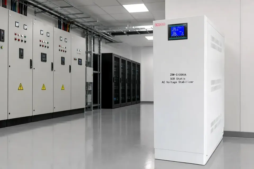
Three devices, three jobs Hold the slow error. A ZBW-S SCR static stabilizer holds 380V out of a 304-456V input at ±1-3 per cent, above 95 per cent efficiency, with no additional waveform distortion, which matters with a rectifier front end.
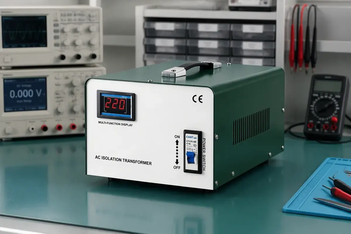
Separate the console branch. An ODK single-phase isolation transformer, 300VA to 2000VA at 220V to 220V with class F insulation and 2500V withstand, puts galvanic separation between console, workstation and building earth, where leakage and common-mode noise are actually won.
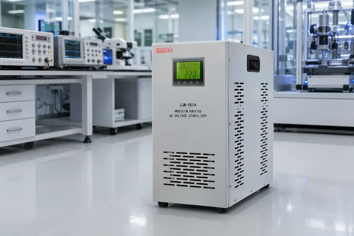
Tighten the single-phase side. Where console and review station need a firm 220V, a JJW precision purified stabilizer covers 1kVA to 30kVA at ±1 per cent with distortion under 3 per cent.
Carry the console through the event. A UPS keeps the record and reconstruction alive across a sag, but not the gantry: rotor and tube want tens of kilowatts for seconds.
Where each answer stops working A stabilizer corrects only what it reaches in time, and a static unit passes harmonics through, so distortion the scanner makes downstream stays at the load.
An isolation transformer does not regulate: feed it 350V and 350V comes out, isolated. The ODK range ends at 2000VA, so it belongs on the console branch, never on the gantry supply.
If the feeding transformer is undersized, none of the three is the fix: a dedicated transformer for the imaging suite changes source impedance itself, and the sag disappears instead of being masked. Earthing is not a product either; a stabilizer on a poor earth still lets interference through.
Conclusion Measure for a week at the terminals before buying. A steady offset on a weak grid takes a static stabilizer sized on real load; interference and leakage on the console branch takes an isolation transformer inside its 2kVA range; a one-second dip at compressor start is a source-impedance problem first and a UPS decision second. The trade-offs behind that choice are in relay, servo and SCR stabilizers; the room checklist is on the medical imaging application page.
Technology · Selection · Industrial