
Adding a Second CT: Imaging Suite Capacity Check
The corridor light dims when the new scanner spins
A hospital adds a second CT beside the first. Alone it passes acceptance; in service every spiral dims the corridor lighting, the older scanner logs a tube-voltage warning in the same second, and the nurse-station UPS transfers. The panel reads 415 V idle and 371 V for a third of a second into a spiral.
Why a scanner averaging 20 percent behaves like a full feeder
Nameplate kVA describes the worst instant the generator and rotor can demand, not the daily average, which sits near a fifth of it.
Pulse shape: rotor acceleration and the generator take several times the running average for hundreds of milliseconds. The supply sees a step, not a load, and a step is answered by impedance.
Coincidence: one scanner images for perhaps a third of the day. Two on one schedule list overlap often enough that the design case is both spinning, so the question is what two need in the worst overlapping minute.
The number worth measuring first
Everything follows from the impedance behind the imaging panel. Log its voltage with both scanners idle, capture the same point during a known acquisition at ten samples per second, and divide the drop by the current: 40 V lost at 300 A is roughly 0.13 ohm, a weak feed and the reason the corridor lights answer to the tube.
Estimate it beforehand: 630 kVA at 4 percent is near 0.010 ohm at 400 V, and cable often adds more, so a feeder that suited one scanner becomes the dominant term for two.
Three checks before anything is ordered
Spare capacity is not nameplate minus average. Substation spare is quoted from hourly demand, on which an imaging feeder never looks busy. Size for both scanners pulsing and keep the dedicated transformer at or below about 60 percent of rating.
Read the dip at the scanner terminals. The feeder adds its own drop, so 6 percent at the panel can be 10 percent at the gantry, enough for a tube-voltage interlock on one unit and a battery transfer on the other.
Fix the window you can correct. A unit with a 304 to 456 V input window holds 380 V while the feeder sits at 330 V; below 304 V it transfers to mains. That figure protects a scan, not the kVA rating.
Three routes and what each costs
Source first. A dedicated transformer and feeder sized for both scanners pulsing removes the cause and protects the suites already complaining, at the cost of floor space, a shutdown and a utility review.
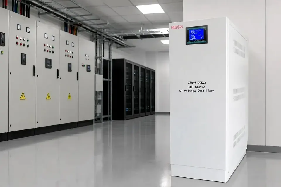
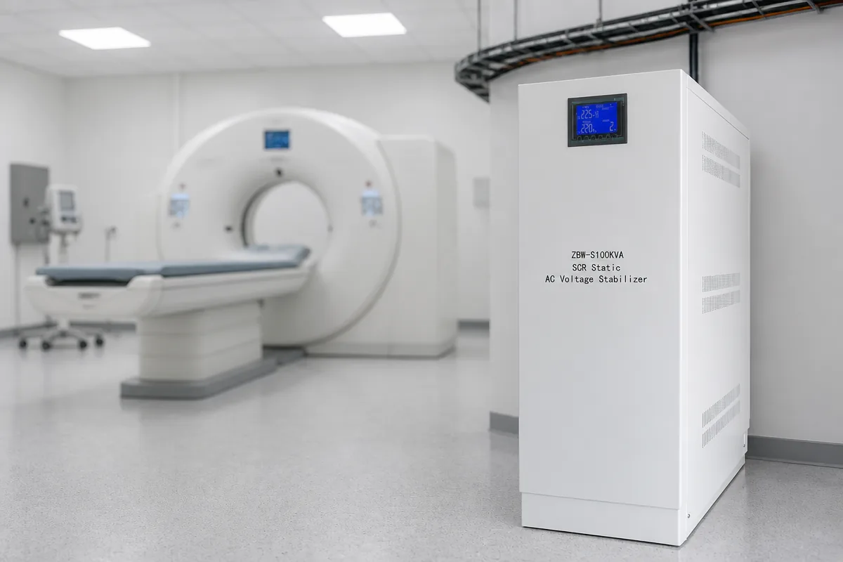
Regulate at the imaging panel. A ZBW-S SCR static stabilizer covers 10 to 3500 kVA, 304 to 456 V input, 380 V output, accuracy settable from 1 to 3 percent, efficiency above 95 percent, no added waveform distortion, per-phase regulation and seamless bypass. Size it on pulsed current with a declared short-time overload, not on the nameplate.
Clean the console branch separately. Console, workstation and injector controller run on single-phase 220 V: a JJW precision purified stabilizer from 1 to 30 kVA, 187 to 253 V input, 220 V at plus or minus 1 percent, holds the reporting chain for a fraction of the cost. Where the complaint is leakage, the ODK single-phase isolation transformer runs 300 VA to 2000 VA.
Where this stops working
A stabilizer stores no energy: below its window, or beyond its short-time overload, it bypasses and the scanner sees what it saw before.
It cannot repair an upstream cause: where the feeder shares a transformer with chillers and lifts, the dip is made before the panel and the stabilizer rides it out for one suite while everything else sags.
Imbalance is separate: a unit regulating its phases together passes uneven single-phase loading straight through. Capacity added from an hourly record is added blind.
Conclusion
Measure the impedance behind the panel first. High impedance means capacity has to come from the source, a stabilizer buying time only inside its window; a sound source with a shallow repeated dip makes a static unit sized on pulsed current the cheaper answer, console branch cleaned separately at 220 V. Device boundaries are in CT and MRI power conditioning; the room checklist is on the medical imaging application page.
Selection · Technology · Industrial