
Relay Voltage Stabilizer: How Tap Switching Works
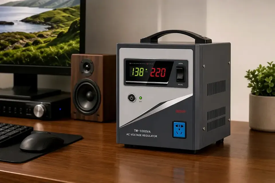
What is actually inside Take the lid off a single-phase relay stabilizer and there are four things: an auto-transformer with a tapped winding, a bank of power relays, a control board with a voltage-sensing divider, and the protection stage. There is no motor, no carbon brush and no thyristor in the main current path.
The winding is the whole mechanism. Instead of one fixed ratio, the transformer exposes a series of taps, each giving a different turns ratio between input and output. Choosing a tap is choosing a ratio. Nothing else in the machine regulates anything.
That is why the relay type stays cheap at small ratings: the parts are a transformer and a set of switches, both made in enormous volume. In the TM series the transformer is the heaviest object in the enclosure and the relay bank sits next to it on the same chassis.
The loop: sample, compare, switch, hold Sample. The control board measures the output voltage continuously through a resistor divider, many times per mains cycle.
Compare. The reading is checked against the set point — 220V on a single-phase unit — with a dead band on either side. Inside the band, nothing happens. A machine that switches nothing is working correctly, not idling.
Switch. When the reading leaves the dead band, the board drives the relay that corresponds to the next tap up or down. One contact opens, another closes, the effective turns ratio changes, and the output moves by exactly one step.
Hold. The new tap holds the output back inside the band. Then the input moves again and the cycle repeats: sample, compare, switch, hold.
Note what is not in that list. There is no feedback loop trying to land on an exact voltage, no continuously variable element, no integration. The controller is making a discrete choice from a fixed menu of ratios.
The staircase: accuracy and contact life are the same number The output of a tap-changing regulator is not a line. It is a staircase, and the height of one step is the single number that governs everything else.
If a design is quoted at plus or minus A per cent, adjacent taps differ by roughly 2A per cent, and the output can sit anywhere inside that band:
- at plus or minus 10 per cent on 220V, the band is 198V to 242V, and one step is about 44V; - at plus or minus 8 per cent, 202V to 238V, one step about 35V; - at plus or minus 5 per cent, 209V to 231V, one step about 22V; - at plus or minus 3 per cent, 213V to 227V, one step about 13V.
So the accuracy figure on the nameplate is really a statement about step size. Now count how many ratios that takes across an input window. The floor is the logarithm of the window ratio divided by the logarithm of one plus the step:
- a 100V to 260V window is a ratio of 2.6; - at 20 per cent steps, log 2.6 over log 1.20 is about 5.2, so six positions; - at 16 per cent steps, about 6.4, so seven; - at 10 per cent steps, about 10; - at 6 per cent steps, about 16.
Those are lower bounds on distinct ratios, not a bill of materials: real designs combine tap sections to reach more ratios with fewer relays. But the direction is unavoidable. Every extra position is another winding section, another relay, another driver channel and more board area. This is why our relay family — TM, BTM and WTM — is quoted at plus or minus 8 or 10 per cent, while the servo and compensated families are quoted at 3. It is not a quality ranking. It is a different point on the same cost curve.
There is a second cost, and it is the one buyers never see. Narrow the step and a given amount of grid drift crosses more thresholds. Switching count rises with accuracy. A plus or minus 10 per cent machine on a feeder wandering 15V might change tap a few times an hour. A plus or minus 3 per cent machine on that same feeder changes tap continuously, and every change is a contact that opens under load.
Which is why designers add hysteresis: widen the dead band, or add a switching delay of a few seconds, so the unit does not chatter at a threshold. Both of those eat accuracy. The number on the nameplate is therefore a compromise between accuracy, contact life and stability, and the buyer can only see one of the three.
The gap between taps is 10 to 30 milliseconds Tap changing is break-before-make. A general-purpose power relay of this class closes in roughly 8 to 20 milliseconds and releases in 5 to 10, so the transfer leaves the output open for something like 10 to 30 milliseconds.
What each load does with a 20 millisecond interruption:
- Incandescent and halogen lamps dim visibly. Harmless. - Modern switch-mode supplies with 16 milliseconds or more of hold-up ride straight through. Most consumer electronics. - Desktop power supplies sit at the edge. The ATX specification asks for 16 milliseconds at full load; a 20 millisecond gap at 90 per cent load can reset the machine. - Downstream AC contactors are the real risk. A coil that drops out on a 20 millisecond dip makes its motor restart afterwards, and a restart is a much bigger event than the dip. - Variable frequency drives usually ride through 20 to 50 milliseconds on their DC link. - Appliance clocks and timers reset. - Medical, laboratory and metering equipment is simply the wrong load, at any relay count.
The engineering rule that follows: never put a relay stabilizer in front of a load whose own controls reset on a 20 millisecond dip. Put it in front of loads that accept one.
Where the relay type still wins Cost per kVA. No servo motor, no brush gear, no SCR heat sink and its driver. For 500VA to 10KVA single phase it is the cheapest way to hold 220V, and at the small end nothing else is close.
Waveform fidelity. A passive transformer does not chop, phase-cut or pulse-width modulate. Input distortion comes out as output distortion, largely unchanged. Feed a waveform-sensitive load and it keeps its waveform.
Surge tolerance. Transformer copper and a relay rated for the current survive motor starting far better than a carbon brush or a semiconductor junction. A pump pulling six times full-load current for two seconds is an ordinary event here.
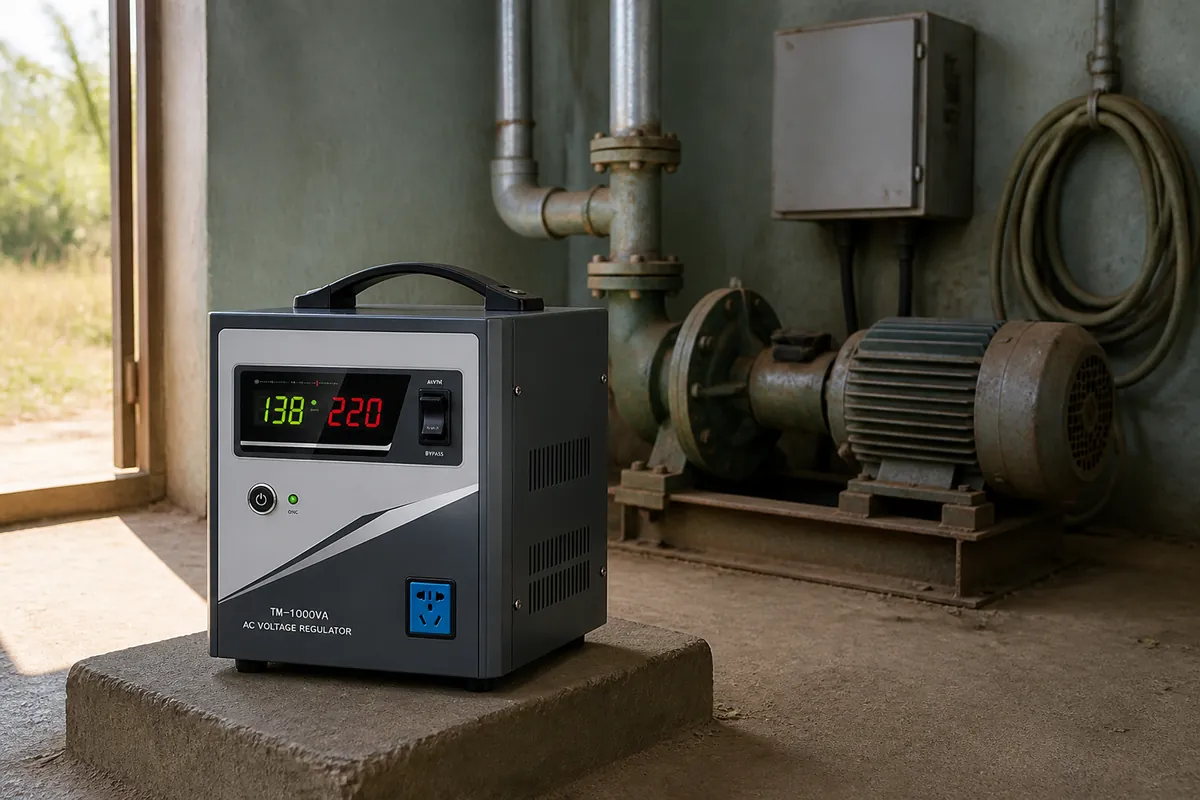
Standby loss. At a held tap the only losses are core and copper. There is no continuous switching loss, no idling servo, no gate drive. Our relay units are quoted above 95 per cent efficiency, and a stable supply means almost no switching at all.
Serviceability. The failure points are four items, all standard: relay, transformer, control board, fuse. A local electrician with a multimeter can find them, and the parts are generic rather than proprietary.
Environment. Relay and transformer tolerate heat, humidity and dust better than a forced-air electronic stage does. Our TM is rated minus 10 to plus 40 degrees Celsius with no derating for altitude or dust beyond that.
No harmonic injection. It is a passive magnetic device. It does not push switching harmonics back into the grid.
Where it does not The accuracy is coarse. Plus or minus 8 or 10 per cent on 220V means 202V to 238V, or 198V to 242V. That is not "220V" by any strict reading. UPS input windows, laboratory instruments and imaging equipment will not accept it.
The 10 to 30 millisecond gap, as above. For an uninterruptible load the answer is a different product, not a bigger relay stabilizer.
Contact life is the real service interval. A power relay in this class is quoted around 10 to the fifth electrical operations at rated load. At a hundred operations a day that is 36,500 a year, so end of life arrives in under three years. On a feeder that chatters, at a thousand operations a day, it arrives in months. The classic failure is a welded contact: the output then sits permanently on whichever tap it welded to, which looks like a regulation fault and is actually a worn switch.
High current is where the economics break. Above a few tens of kVA per phase, a relay that can break the current gets large and expensive, and paralleling poles never shares current evenly. That is the point where servo or static regulation becomes the cheaper answer rather than the better one.
It locks out rather than stretches. Below the bottom of the input window — 100V on TM, 80V on WTM, 45V on the custom wide version — the unit protects and stops regulating. It does not try harder. If the site spends hours a day under 100V, the fix is a wider window or a different technology, decided before the order, not after.
The spec sheet that answers the question Five numbers decide whether a relay stabilizer fits a site, and all five should be written down before comparing prices:
1. Input window, as a real range, not a headline: 100 to 260V, 80 to 260V, or custom 45 to 280V. 2. Quoted accuracy at both ends of that window, because the worst case is at the extremes. 3. Step count, if the supplier will disclose it. One step tells you more than any accuracy claim. 4. Relay rating against actual load current, including inrush. A 10kVA unit on a 3kW pump is not oversized; it is correctly sized for starting. 5. Switching delay and dead band settings, and whether they are adjustable. A long delay protects the relay and leaves the load unprotected.
Relay, servo, or SCR One line each: the relay type switches taps and regulates in steps; the servo turns a carbon brush along an exposed winding and regulates continuously, at the price of a wear part; the static type switches with thyristors or IGBTs, has no moving contact, responds in a cycle, and brings switching harmonics with it. The full comparison, including where each one fails, is in relay, servo and SCR stabilizers compared.
If the input window is the deciding factor rather than the technology, the trade between a standard and a wide window is worked through in wide input versus standard relay stabilizer.
Conclusion A relay stabilizer is a transformer with a switch, and that is the honest description. It is cheap, quiet, waveform-honest and mechanically robust, and it regulates in steps whose size you can calculate from the accuracy figure before you buy.
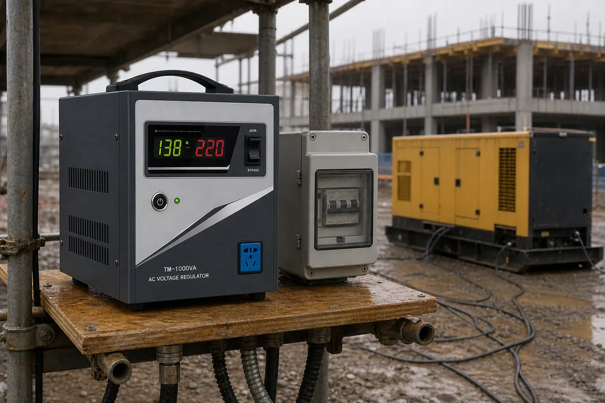
Choose it for loads that accept a 20 millisecond dip and an 8 per cent band: pumps, heaters, refrigeration, lighting, small workshops, and sites on a generator whose output drifts slowly rather than flickering. Do not choose it for a scanner, a laboratory bench, or anything with its own contactor logic downstream. When the load is a mixture, size it on the motor starting current rather than the running load — the method is in how to size a voltage stabilizer, and typical mixed industrial loads are listed under general applications.
Technology · Single-phase · Relay